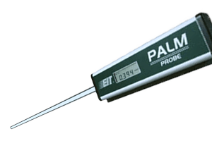
PALM Probe
A probe radiometer for UV measurement and process control in select applications
The PALM Probe radiometer from EIT addresses UV measurement and process control in areas where it has been difficult to pass a radiometer through the process. The use of UV inks and coatings has grown in label and web markets, and the PALM Probe offers safe, reliable measurement for these and other applications.
The word PALM is an acronym for Production Ambient Light Measurement. The PALM Probe UV radiometer has an extremely wide dynamic range allowing it to read from very low levels of UV light (as in fluorescent bulbs) to very high levels of UV (found in powerful UV curing systems).
The physical conditions inside a UV curing chamber are harsh. An instrument must withstand wide temperature variations. A tremendous amount of electrical energy is used to excite the UV bulb. The PALM Probe is designed to withstand the harsh physical conditions of the UV curing chamber while protecting the operator and instrument from damage or electrical shock. Potentially lethal voltages exist in UV curing systems.
Although the light guide was designed to reduce the risk of shock, the user should avoid contact with the high voltage areas in the UV housing. With this device, the user holds the body of the instrument and inserts only the light guide under the UV source.
Ultraviolet, visible and infrared light radiation of all wavelengths impinges on the input aperture at the tip of the PALM Probe light guide. The light is directed down the light guide to the base of the probe body, where the UV filter passes the UV light of interest to the photodetector. The photodetector converts the light energy to a current that is proportional to its intensity. The signal is conditioned, digitized, processed and displayed on the LCD of the PALM Probe.
The light guide is constructed of a steel alloy and coated with a non-conductive ceramic coating to insulate and protect the user from accidental shock while taking measurements. The guide is further isolated from the body by a non-conductive Delrin block. The body contains the optics, electronics, battery and display functions of the unit. It can be held either with an over or underhand grip. The raised membrane switches are easy to operate with either hand.
The PALM Probe has a very wide dynamic range that automatically adjusts itself for the user. For example, it can measure light from approximately 100 mW/cm2 (µW/cm2) up to 10 W/cm2. The decimal point in the LCD “floats” over three places to cover the wide dynamic range on the unit.
The PALM Probe display allows the user to alternate between Watts-Joules-Seconds during data collection and after a reading or run has been made. The SELECT button allows the user to toggle between the values.
When collecting irradiance data with the PALM Probe, the display will change as the probe changes position under the UV source. As the aperture opening moves into the focused peak irradiance area of the UV source, the reading increases. Variations in irradiance may also be seen when the probe is moved along the length of a UV bulb. The LCD display automatically scales and adjusts as the probe takes readings. Pressing the RUN / STOP button stops the collection of data and the highest irradiance value measured during the collection of data will be displayed. Most users will find that the irradiance value (W/cm2) displayed is the most important value collected by the probe when it comes to process control for a particular application.
UV energy density or dose incorporates time into the irradiance measurement. The probe displays the energy density or dose value in Joules (J/cm2) on the LCD. The dose is an integration of the area under the irradiance curve. The dose reading increases as the reading continues. The speed at which the dose increases depends on the irradiance value. Switching to the built-in timer in the probe helps monitor the time component of the dose reading for more consistent results. Placement of the probe in the same location is important in order to get consistent and repeatable irradiance values to calculate dose readings.
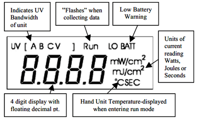
The following diagram shows all the available LCD Displays on the PALM Probe. In operation, the display is easy to read and understand as the user only sees the segments on the display that pertain to current reading.
The PALM Probe must be placed in a regular and repeatable location to achieve consistent results. EIT has developed two accessories to help with this.
The first accessory is supplied with each unit and attaches over the light guide to allow it to be positioned to the same “stop” depth each time the probe is used to take a reading.
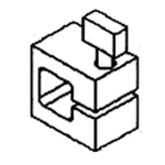
The second accessory is a Locator Kit. Mounted on the system, it allows the light guide to be inserted in the same location each time. The kit can mount in either direction (shown below) and is available without the hinged door.
The readings from the PALM Probe can be coordinated with the readings obtained from EIT online monitoring instruments. When conditions are ideal (clean reflector, new UV lamps), the EIT displays can be set to read 100% UV intensity. Baseline readings of the UV intensity can be obtained with the probe. The UV will generally decrease over time as the reflectors and UV bulbs change. The readings displayed on the EIT online monitors can be compared to the readings on the probe. The online monitors provide continuous monitoring, including alarm functions and feedback information. The probe also allows users to compare readings between systems.
- Measure UV system performance, particularly in applications where measurement space is limited or difficult to access
- Establish, document and maintain UV process windows
- Meet ISO, quality and customer requirements for SPC / SQC
- Verify readings from online sensors; coordinate relative percentage type readings from online displays to absolute units
- Multiple uses from production curing (high irradiance) to stray hazard (low irradiance) applications
| Electrical Specifications | |
|---|---|
| Part # | UV2314 |
| UV Range | 100 µW/cm2-10 W/cm2 |
| UV Spectral Response | UVA 320nm, Visible 395–445nm |
| Display | LCD with 4 digits and floating decimal point |
| User Interface | Two raised membrane switches |
| Operating Temperature Range | Probe Body 0–70°C |
| Time-out period | 10 minutes |
| Batteries | Two AA alkaline batteries |
| Battery Life | 25 hours run time |
| Mechanical Specifications | |
|---|---|
| Overall Length | 25.75” ( 65.4 cm) |
| Probe Body Length | 7.5” ( 19.0 cm) |
| Light Guide Length | 18.25” (46.4 cm) |
| Weight | 21 oz (596 grams) |
| Light Guide Temperature Resistance | 750°F (400°C) on a continuous basis; much higher for measurement length exposures |